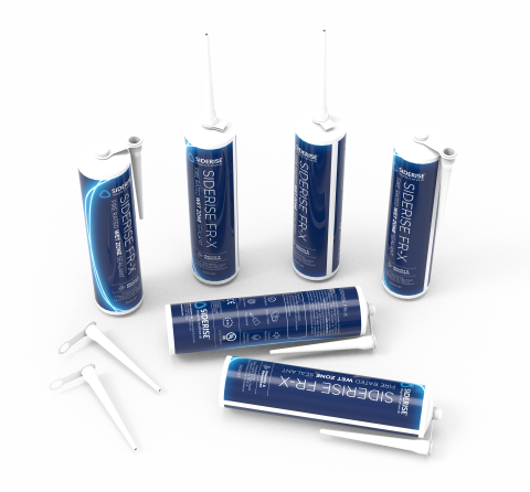
RH Rainscreen Horizontal Open State Cavity Barrier
Open state cavity barriers designed to allow ventilation and drainage in rainscreen façades whilst offering fire protection.
Ventilation meets protection
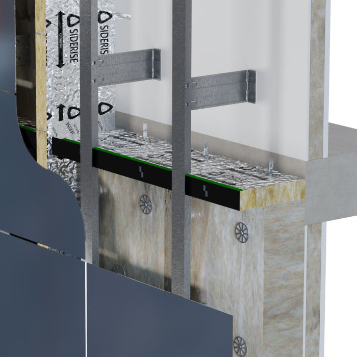
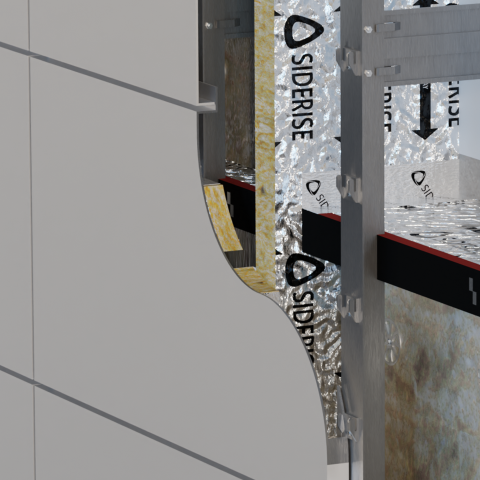
RH Rainscreen Horizontal Open State Cavity Barrier has been developed to meet the complex requirements of pressure equalised and drained and back ventilated (DBV) rainscreen systems. The stone wool Lamella barrier incorporates an integral strip of intumescent material along the leading edge. Mechanically fixed to the inner wall construction using full penetration fixings for positive restraint, it leaves the cavity open to allow daily ventilation and drainage. In a fire, the intumescent expands in a matter of minutes until the gap is closed and a fire seal is formed, preventing the spread of fire.
We have developed a range of open-state cavity fire barriers for different air gap sizes and fire resistance performance requirements — RH25 for air gaps up to 25mm and RH50 up to 50mm
RH Rainscreen Horizontal Cavity Barrier has been tested to ASFP TGD19 ‘Fire Resistance Test of Open State Cavity Barriers’ using principles of BS EN 1363-1
The performance of RH Horizontal Cavity Barrier is IFC Certified (IFCC 1712)
RH Horizontal Cavity Barrier products have all achieved CCPI assessed status, except for the new product addition RH25 120/120, which is awaiting approval. This provides greater confidence that the product information we publish about these products is clear, accurate, up-to-date, accessible, and unambiguous — and is checked and managed by competent people.
RH Horizontal Cavity Barrier has been used in cladding systems assessed under multiple large-scale fire tests, including BS 8414 and NFPA 285.
The leading edge is finished with a black film to register as a ‘shadow-line’ behind open joints in the cladding.
To confirm long-term durability, RH Cavity Barrier has been put through EOTA TR 024 ‘Type X’ accelerated age testing, the harshest category, which replicates exposure to rain, UV, high temperatures, and frost and thaw cycles.
Siderise RH ‘Open State’ horizontal cavity barriers have been specifically developed to meet the requirements for cavity barriers used in drained and ventilated façades. Their use ensures that the system will drain moisture within the façade construction whilst maintaining airflow in normal service. In the event of fire, the intumescent on the leading edge rapidly expands, closing the ventilation gap to provide an effective fire seal.
Siderise has developed two ‘Open State’ (open void) horizontal solutions: RH25 for air gaps up to 25mm and RH50 for air gaps up to 50mm.
Siderise RH ‘Open State’ horizontal cavity barriers are compliant with current market requirements and have been tested to ASFP Guidance: ‘Open State’ Cavity Barriers used in External Envelope or Fabric of Buildings, utilising principles of EN 1363-1, referred to as ASFP Technical Guidance Document –TGD 19 (EN 1364-6).
Third-party Certification
Siderise was the first manufacturer to achieve Third-party certification for Rainscreen Cavity Barriers.
For current details of Siderise certified 'Open State' Cavity Barriers, including the testing and scope of our Third-Party Certification, please refer to IFC Certification IFCC 1712.
This Certificate is available from our online Technical Resources or by contacting our Technical Support department: [email protected]
CCPI assessed status
Siderise RH ‘Open State’ horizontal cavity barrier products have been assessed under the CCPI scheme except for the new product addition RH25 120/120, which is awaiting approval.
Assessment Number: 000800105/1226
Siderise RH ‘Open State’ horizontal cavity barriers consist of a non-combustible stone wool lamella core, with reinforced aluminium foil faces. This primary seal has a reaction to fire performance to Class 'A1'. The exposed leading edge is also sealed with aluminium foil. Whilst the base material is water repellent and non-hygroscopic, this predominantly enclosed arrangement affords an added degree of weather protection to the core material.
Siderise RH ‘Open State’ horizontal cavity barriers incorporate a continuous reactive intumescent strip which is bonded to the leading edge. The intumescent material has a reaction to fire performance to Class 'E'. In the event of exposure to fire, the intumescent rapidly expands and fully seals the purposely designed ventilation gap formed at the time of installation, between the barrier and the rear of the cladding.
As standard, the range includes a choice of products to suit either 25mm air gaps - referred to as RH25 - or 50mm air gaps - referred to as RH50. Both options are available with either galvanised mild steel (G) or stainless steel (S) fixing brackets as part of the system.
The specific horizontal cavity barrier system is then referred to as either RH25G, RH25S, RH50G or RH50S accordingly. The choice of brackets is usually determined by the rainscreen system designer according to project exposure and/or location.
The leading edge of the horizontal cavity barriers is encapsulated in a polymer film. As standard, the film is black to register as a ‘shadow-line’ behind open joints in the cladding.
For product identification purposes, the top edges of the film used on the RH25 and RH50 cavity barriers are colour-coded and labelled to show the product fire performance rating.
Siderise ’Open State’ horizontal cavity barriers have been tested in accordance with ASFP TGD19 (prEN 1364-6): ’Open State’ Cavity Barrier used in External Envelope or Fabric of Buildings. This test method specifies a procedure for determining the fire resistance of ’open state’ cavity barriers when subjected to the standard fire exposure conditions and performance criteria stipulated in EN 1363 Part 1: 2012.
The tests have been undertaken to assess the ability of the horizontal ’open state’ cavity barrier products to reinstate the fire resistance of a pre-cast, aerated concrete supporting construction. This is the standard assembly for testing such cavity barrier products as it allows the performance of the individual barrier to be classified.
We advise that all ‘RH’ Open State Cavity Barriers are positioned either flush or projecting in front of the thermal insulation.
Product Fire Performance
Siderise RH25 ’Open State’ horizontal cavity barrier for maximum 25mm air gaps
Siderise has tested horizontal cavity barriers with a 25mm air gap to the ASFP TGD19 method. During the fire tests, the seals achieved full effective closure in under 5 minutes. Seal temperatures remained below a 180°C rise during this activation period and maintained the EI requirements for up to E 120 and I 120. See Table 1 for details.
Siderise RH50 ’Open State’ horizontal cavity barrier for maximum 50mm air gaps
Siderise has tested horizontal cavity barriers with a 50mm air gap to the ASFP TGD19 method. During the fire tests, the seals achieved full effective closure in under 5 minutes. Seal temperatures remained below a 180°C rise during this activation period and maintained the EI requirements as detailed in Table 1 for up to E 60 and I 60. See Table 1 for details.
System Fire Performance
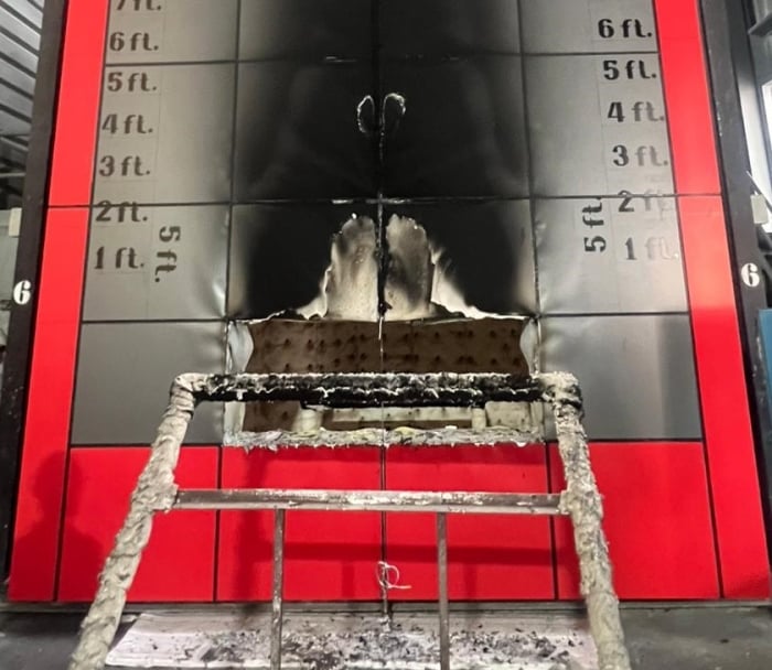
Siderise cavity barrier products have been used in several large-scale system tests such as BS 8414 (1&2) and NFPA 285. These may be used to evaluate the performance of the Siderise cavity barriers within a complete cladding system. The rules for extended application of results from BS 8414 tests are subsequently defined in BS 9414.
For information regarding performance and assembly details in system tests please see our system tests page.
Table 1: Fire classification performance to TGD 19 (prEN 1364-6)
| Product Ref | Colour | Void Range (mm) | Air Gap (mm)** | Integrity (mins) | Insulation (mins) | Third-party Certification |
|---|---|---|---|---|---|---|
|
RH25-120/90* |
Grey |
0 - 25 |
≤ 25 |
120 |
90 |
IFCC 1712 |
|
RH50-60/60* |
Blue |
0 - 50 |
≤ 50 |
60 |
60 |
IFCC 1712 |
|
RH25-90/30 |
Green |
26 - 425 |
≤ 25 |
90 |
30 |
IFCC 1712 |
|
RH25-60/60 |
Orange |
26 - 425 |
≤ 25 |
60 |
60 |
IFCC 1712 |
|
RH25-90/60 |
Purple |
26 - 300 |
≤ 25 |
90 |
60 |
IFCC 1712 |
|
RH25-120/60 |
Yellow |
26 - 425 |
≤ 25 |
120 |
60 |
IFCC 1712 |
|
RH25-120/90 |
Grey |
26 - 425 |
≤ 25 |
120 |
90 |
IFCC 1712 |
|
RH25-120/120*** |
White |
75 - 425 |
≤ 25 |
120 |
120 |
IFCC 1712 |
|
RH50-30/30 |
Red |
51 - 300 |
≤ 50 |
30 |
30 |
IFCC 1712 |
|
RH50-60/60 |
Blue |
51 - 300 |
≤ 50 |
60 |
60 |
IFCC 1712 |
*Intumescent strip only.
** To allow for on-site conditions, RH25 can be used for air gaps of 25 +/-3mm and RH50 can be used for air gaps of 50 +/-5mm.
*** Tested with min. 50mm thick stone wool thermal insulation (classified A1 to EN 13501-1) above and below the cavity barrier.
See IFC Certification IFCC 1712 for further details.
RH open state cavity barriers are generally tested with phenolic insulation used above and below the cavity barrier, with TGD 19 setting out a ranking for insulation products. Stone wool and glass wool insulation are considered less onerous, with PIR, PUR and EPS considered more onerous. The field of application for this standard places limits on the distance between the front face of the insulation and the leading edge of the cavity barrier when combustible insulation is utilised.
Table 2: Bracket fixing requirements and barrier dimensions for RH25 (voids greater than 75mm) and RH50 (voids greater than 100mm)
| Product Ref | Void Range (mm) | Air Gap (mm) | Barrier Dimensions T x W (mm) | Length (mm) | Bracket Requirement |
|---|---|---|---|---|---|
|
RH25-90/30 |
76 - 250 |
25 |
75 x Void -25 |
1200 |
3no RS 350 G/S |
|
251 - 350 |
25 |
75 x Void -25 |
1200 |
3no RS 450 G/S |
|
|
351 - 425 |
25 |
75 x Void -25 |
1200 |
3no RS 550 G/S |
|
|
RH25-60/60 |
76 - 250 |
25 |
90 x Void -25 |
1200 |
3no RS 350 G/S |
|
251 - 350 |
25 |
90 x Void -25 |
1200 |
3no RS 450 G/S |
|
|
351 - 425 |
25 |
90 x Void -25 |
1200 |
3no RS 550 G/S |
|
|
RH25-90/60 |
76 - 250 |
25 |
90 x Void -25 |
1200 |
3no RS 350 G/S |
|
251 - 300 |
25 |
90 x Void -25 |
1200 |
3no RS 450 G/S |
|
|
RH25-120/60 |
76 - 250 |
25 |
120 x Void -25 |
1200 |
3no RS 350 G/S |
|
251 - 350 |
25 |
120 x Void -25 |
1200 |
3no RS 450 G/S |
|
|
351 - 425 |
25 |
120 x Void -25 |
1200 |
3no RS 550 G/S |
|
|
RH25-120/90 |
76 - 250 |
25 |
120 x Void -25 |
1200 |
3no RS 350 G/S |
|
251 - 350 |
25 |
120 x Void -25 |
1200 |
3no RS 450 G/S |
|
|
351 - 425 |
25 |
120 x Void -25 |
1200 |
3no RS 550 G/S |
|
|
RH25-120/120 |
76 - 250 |
25 |
120 x Void -25 |
1200 |
3no RS 350 G/S |
|
251 - 350 |
25 |
120 x Void -25 |
1200 |
3no RS 450 G/S |
|
|
351 - 425 |
25 |
120 x Void -25 |
1200 |
3no RS 550 G/S |
|
|
RH50-30/30 |
101 - 250 |
50 |
75 x Void -50 |
1200 |
3no RS 350 G/S |
|
251 - 300 |
50 |
75 x Void -50 |
1200 |
3no RS 450 G/S |
|
|
RH50-60/60 |
101 - 250 |
50 |
90 x Void -50 |
1200 |
3no RS 350 G/S |
|
251 - 300 |
50 |
90 x Void -50 |
1200 |
3no RS 450 G/S |
Please note:
- RH25-120/120 was tested with min. 50mm thick stone wool thermal insulation (classified A1 to EN 13501-1) above and below the cavity barrier.
- 'T' refers to barrier thickness. 'W' refers to barrier width.
- Brackets are available in two forms: (G) denotes galvanised steel brackets and (S) denotes stainless steel brackets.
- Brackets must be installed at 400mm centres based on a 1200mm strip. For lengths ≤800mm 2no brackets must be used, with spacing reduced pro-rata. For lengths ≤200mm a single centrally positioned bracket must be used. Lengths <100mm should be avoided by cutting down the adjacent barrier accordingly.
- All brackets are to be suitably fixed to the substrate with non-combustible fixings.
- All brackets penetrate the product at mid-thickness. The protruding split ends should be counter-folded to retain the product, except for RH50-60/60 and RH25-120/120. For RH50-60/60, ensure the split end facing down overlaps with the intumescent face. For RH25-120/120, the bracket should overhang the barrier by 15mm then one of the split ends should be bent upwards and the other trimmed flush with the leading face of the barrier.
- Please refer to separate installation instructions.
Table 3: Screw fixing requirements and barrier dimensions RH25 (voids up to 75mm) and RH50 (voids up to 100mm)
| Product Ref. | Void Width (mm) | Air Gap (mm) | Barrier Dimensions T x W (mm) | Length (mm) | Fixing Requirement |
|---|---|---|---|---|---|
|
RH25-120/90* |
0-25 |
≤ 25 |
75 x 1.5 |
1200 |
3no Screws |
|
RH50-60/60* |
0-50 |
≤ 50 |
35 x 3 |
1200 |
3no Screws |
|
RH25-90/30 |
26-30 |
≤15 |
75 x 15 |
1200 |
3no Screws |
|
31-35 |
≤20 |
75 x 15 |
1200 |
3no Screws |
|
|
36-40 |
≤ 25 |
75 x 15 |
1200 |
3no Screws |
|
|
41-45 |
≤ 25 |
75 x 20 |
1200 |
3no Screws |
|
|
46-75 |
25 |
75 x Void -25 |
1200 |
3no Screws |
|
|
RH25-60/60 |
26-30 |
≤15 |
90 x 15 |
1200 |
3no Screws |
|
31-35 |
≤20 |
90 x 15 |
1200 |
3no Screws |
|
|
36-40 |
≤ 25 |
90 x 15 |
1200 |
3no Screws |
|
|
41-45 |
≤ 25 |
90 x 20 |
1200 |
3no Screws |
|
|
46-75 |
25 |
90 x Void -25 |
1200 |
3no Screws |
|
|
RH25-90/60 |
26-30 |
≤15 |
90 x 15 |
1200 |
3no Screws |
|
31-35 |
≤20 |
90 x 15 |
1200 |
3no Screws |
|
|
36-40 |
≤ 25 |
90 x 15 |
1200 |
3no Screws |
|
|
41-45 |
≤ 25 |
90 x 20 |
1200 |
3no Screws |
|
|
46-75 |
25 |
90 x Void -25 |
1200 |
3no Screws |
|
|
RH25-120/60 |
26-30 |
≤15 |
120 x 15 |
1200 |
3no Screws |
|
31-35 |
≤20 |
120 x 15 |
1200 |
3no Screws |
|
|
36-40 |
≤ 25 |
120 x 15 |
1200 |
3no Screws |
|
|
41-45 |
≤ 25 |
120 x 20 |
1200 |
3no Screws |
|
|
46-75 |
25 |
120 x Void -25 |
1200 |
3no Screws |
|
|
RH25-120/90 |
26-30 |
≤15 |
120 x 15 |
1200 |
3no Screws |
|
31-35 |
≤20 |
120 x 15 |
1200 |
3no Screws |
|
|
36-40 |
≤ 25 |
120 x 15 |
1200 |
3no Screws |
|
|
41-45 |
≤ 25 |
120 x 20 |
1200 |
3no Screws |
|
|
46-75 |
25 |
120 x Void -25 |
1200 |
3no Screws |
|
|
RH25-120/120 |
75 |
25 |
120 x Void -25 |
1200 |
3no Screws |
|
RH50-30/30 |
51-55 |
≤40 |
75 x 15 |
1200 |
3no Screws |
|
56-60 |
≤45 |
75 x 15 |
1200 |
3no Screws |
|
|
61-65 |
≤ 50 |
75 x 15 |
1200 |
3no Screws |
|
|
66-70 |
≤ 50 |
75 x 20 |
1200 |
3no Screws |
|
|
71-100 |
50 |
75 x Void -50 |
1200 |
3no Screws |
|
|
RH50-60/60 |
51-55 |
≤40 |
90 x 15 |
1200 |
3no Screws |
|
56-60 |
≤45 |
90 x 15 |
1200 |
3no Screws |
|
|
61-65 |
≤ 50 |
90 x 15 |
1200 |
3no Screws |
|
|
66-70 |
≤ 50 |
90 x 20 |
1200 |
3no Screws |
|
|
71-100 |
50 |
90 x Void -50 |
1200 |
3no Screws |
*Intumescent strip only.
- RH25-120/120 was tested with min. 50mm thick stone wool thermal insulation (classified A1 to EN 13501-1) above and below the cavity barrier.
- Screw fixings must be installed at 400mm centres based on a 1200mm strip. For lengths ≤800mm 2no screw fixings must be used, with spacing reduced pro-rata. Lengths <100mm should be avoided by cutting down the adjacent barrier accordingly.
- All barriers to be suitably fixed to substrate with non-combustible fixings and washers with a 10-15mm (max.) head diameter.
- For RH25 all screw fixings to penetrate product at mid-thickness. For RH50 all screw fixings to penetrate the top edge of the RH50 intumescent.
- Please refer to separate installation instructions
Thermal conductivity: λ= 0.038 W/m.K (tested foil to foil)
Siderise RH ‘Open State’ horizontal cavity barriers
Table 4: Technical Specification
| Properties | Value |
|---|---|
| Form Supplied |
1200mm long. Supplied pre-cut in width to suit advised void size reduced by the ventilation gap required. |
| Product Finish |
Aluminium foil tape to top and bottom surfaces |
| Appearance |
Black leading edge with coloured tapes to indicate performance |
| Weight |
Precut strips with stone wool from 0.5kg to 4.8kg dependent on grade of product and void width. Intumescent strip only product 0.2kg |
| Thermal Conductivity |
λ = 0.038 W/m.K (tested foil to foil) |
| Reaction to Fire |
The primary stone wool seal is Classified 'A1' to EN 13501-1 The reactive intumescent along the leading edge is Class 'E' to EN 13501-1. This is permitted by Regulation 7(3)(f) - Approved Document B for England & Wales. |
| Resistance to Fire |
For product fire performance see Tables 1, 2 and 3 |
Recyclability
The stone wool core is recyclable.
Third-party verified EPD
Siderise RH 'Open State' horizontal cavity barriers have an Environmental Product Declaration (HUB-0824) in accordance with EN 15804+A2 & ISO 14025 / ISO 21930. Please see EPD in Product Resources or EPD Hub for further information.
60 Year Design Life
To confirm long-term durability, RH Cavity Barriers have been put through EOTA TR 024 ‘Type X’ accelerated age testing. This is the harshest category which replicates exposure to rain, UV, high temperatures, and frost and thaw cycles.
When correctly installed in recommended applications, RH Cavity Barriers have an expected service lifespan of 60 years.
The following information is available upon request or via download from the website:
- Third-party Certification
- Environmental Product Declaration
- Material Data Sheet
- Installation Instructions
- Installation Video
- Standard Details
- NBS Specification Clauses
For technical advice, support, or to request a copy of a test or classification report - please contact: [email protected]
For Installation Training or Site Inspections please contact: [email protected]
For technical advice or support in the Middle East, India or Asia Pacific contact: [email protected]
The information in this datasheet is believed to be accurate at the date of publication. Siderise has a policy of continuous product improvement and reserves the right to alter or amend the specifications of products without prior notice. Siderise does not accept responsibility for the consequences of using the products described outside of the recommendations within this datasheet. Expert advice should be sought where there is any doubt about the correct specification or installation of Siderise products.


Installation
View our installation video
Test data
View our testing data and see how we can help you go beyond on your next façade project
Products
Ancillaries
Single source supply components for compatibility, performance and confidence

Products
Related products
Passive fire protection products designed to work holistically


FAQs
Get quick answers to common queries or contact our team for more advice. Your questions answered.
Yes, our site services engineers combine classroom learning with toolbox training and includes mock-up benchmark installations, free-of-charge.
Yes, brackets are available in two forms: galvanised steel brackets (G) and denotes stainless steel brackets (S)
RH Horizontal Cavity Barrier is available for voids up to 425mm with various fire resistance options, depending on requirements. Please see the Technical Datasheet for full breakdown of available void widths


Contact us
We're here to help you
Call for our main switchboard
Email us for technical enquiries
Email us for site support
Complete the form for the right response
Augmented Reality

Point your camera at the QR code. Tap the banner that appears on your screen.